A practical explanation of tire feeding, low-speed cutting, overload control, screening, steel liberation and downstream processing.
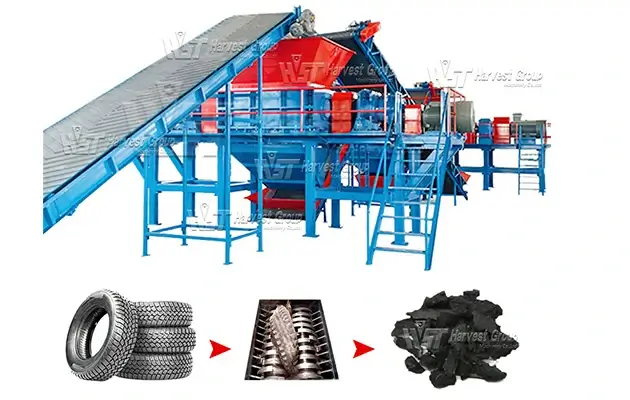
A tire shredder reduces whole tires by pulling them between slow-turning cutter shafts. The electric motors and gear reducers lower the shaft speed and increase torque, while hooked alloy-steel cutters grip the tire and force it into the cutting chamber. Rubber, textile reinforcement, steel belts and bead wire are compressed, stretched and sheared as the shafts turn. The first pass normally produces irregular tire strips or chips rather than finished crumb rubber.
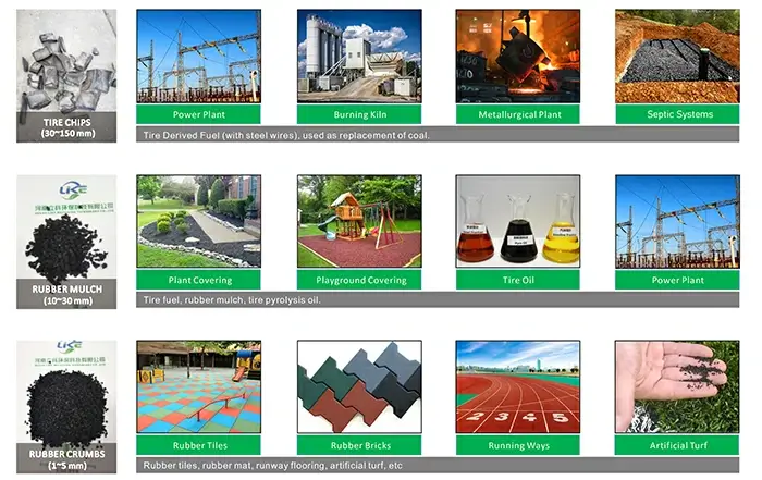
Primary tire chips are often within a broad range of about 50–150 mm, but the actual result depends on the tire type, cutter arrangement and discharge system. When a project requires a narrower size distribution, oversized pieces must be screened and returned for another pass. A complete system may then use a rasper, magnetic separation, fiber separation and granulation to make TDF, wire-free mulch, crumb rubber or fine powder.
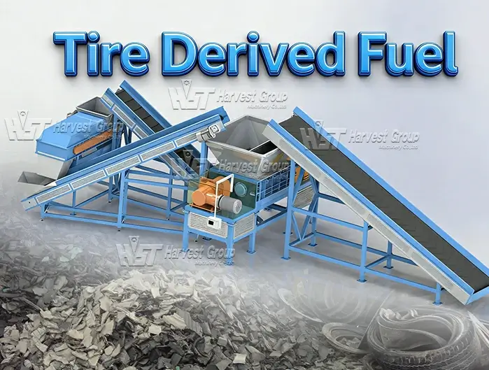
An industrial tire shredder machine performs the first size-reduction step in many tire recycling plants. Its job is not to make a polished final product in one pass. It opens the tire structure, reduces storage volume and prepares the material for screening, steel liberation or finer grinding.
This distinction matters because a tire is a reinforced composite, not a solid block of rubber. The tread and sidewall flex under pressure, the steel belt resists cutting, and the bead contains concentrated high-tensile wire. A tire shredder therefore relies on controlled torque and repeated shearing instead of the high cutting speed used by a conventional saw or slicer.
The output from an open-discharge double-shaft shredder is usually rough and varied in shape. If the buyer needs a specified maximum size, the plant must combine the shredder with suitable screening and return equipment or use an additional size-reduction stage.
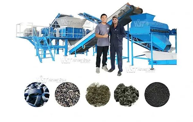
Whole tires normally reach the shredder through a belt conveyor, hydraulic loading device or feed hopper. The correct arrangement depends on tire diameter, plant capacity and loading method. A steady feed gives the cutters time to grip each tire and helps prevent several tires from bridging above the shafts.
Filling the hopper too quickly does not automatically increase hourly production. A sudden cluster of truck tires can raise the motor load, increase reversing frequency and interrupt the discharge flow. In an automatic line, the PLC can use motor current or torque feedback to pause the infeed conveyor until the cutting chamber returns to a normal load.
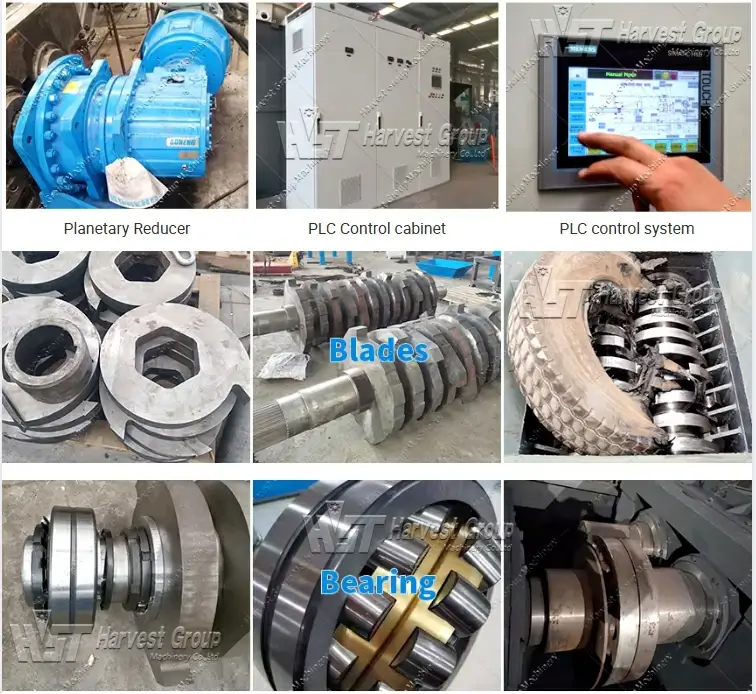
The drive system usually includes electric motors, couplings and heavy-duty gear reducers. The reducer decreases motor speed and multiplies torque before power reaches the cutter shafts. This allows the machine to work through thick rubber and embedded steel without depending on very high rotor speed.
Some large or mobile shredders use hydraulic drives, but the working principle remains similar. The drive must deliver controllable torque, tolerate short load peaks and protect the shafts and reducers when an unshreddable object enters the chamber.
In a double-shaft design, the shafts rotate inward. Cutter hooks catch the tread or sidewall and pull the tire down rather than allowing it to bounce on top of the rotor. As cutters on the two shafts pass one another, their edges create shearing zones that tear the tire into strips and blocks.
The two shafts may not always run at exactly the same speed. Depending on the design, a speed difference can improve the pulling and tearing action. Cutter profile, hook depth, cutter thickness, shaft spacing and the clearance between adjacent parts all influence how the tire enters and breaks apart.
Truck tire beads, folded tire sections or foreign metal can cause a rapid rise in load. When the measured current or torque exceeds the programmed limit, the controller can stop the shafts, reverse them briefly and then restart in the forward direction. This movement redistributes the material and often clears the obstruction without manual intervention.
Automatic reversal is a protection function, not a substitute for correct feeding. If the machine reverses repeatedly, the operator should check the tire mix, feed rate, cutter condition and cutting-chamber clearance. Continuing to force material through can increase wear on cutters, bearings and reducers.
After the tire passes through the cutter shafts, the material falls onto a discharge conveyor. Some primary double-shaft shredders discharge freely and do not contain an internal screen. In that configuration, a trommel, disc screen or other external sizing unit separates acceptable chips from oversized pieces. A return conveyor sends the oversize fraction back to the shredder.
Other shredder designs use a screen beneath the rotor. The appropriate method depends on the machine and the required product. In either case, a stable maximum chip size comes from the complete sizing loop, not from cutter thickness alone.
The first cutter hook deforms the tire and creates a secure bite. Because the tire is hollow and elastic, it may flatten, fold or turn before it is fully drawn between the shafts. Once opposing cutters hold different parts of the carcass, the tire can no longer flex as a single unit.
The rubber is then stretched while the cutter edges apply shear across the tread, sidewall and reinforcement layers. Steel belt cords are cut or exposed as the surrounding rubber separates. The thick bead area usually creates the highest short-duration load because many steel wires are concentrated in a small cross-section.
Material-clearing parts are also important. Depending on the shredder design, fixed cleaners, stripper plates or the geometry around the spacers help push rubber away from the shafts and reduce wrapping. The required clearance must be maintained during service; excessive clearance or heavily worn cutter edges can reduce the gripping action and produce more oversize material.
Mechanical shredding changes the tire’s physical size and exposes embedded reinforcement. It does not reverse vulcanization or chemically break the rubber’s cross-linked molecular structure. Devulcanization, when required, is a separate process.
It is common to describe a tire shredder by a nominal chip size, but actual output is a distribution rather than one exact dimension. A line producing a controlled TDF chip must limit the oversize fraction, while a line feeding a rasper may accept a wider primary range. The following factors work together.
| Factor | How It Changes the Result | What the Operator May Notice |
| Cutter thickness and hook geometry | Influence the initial bite, strip width and tearing pattern | Different chip shapes even when the same tire type is used |
| Cutter sharpness and clearance | Worn edges grip and shear less effectively | More oversize pieces, lower capacity or more frequent reversing |
| Tire construction | PCR, TBR and OTR tires contain different rubber thicknesses and reinforcement | Capacity and chip shape change when the feed mix changes |
| Feed rate | Excess feeding causes load peaks and reduces stable cutting time | Conveyor stops, repeated reversing or uneven discharge |
| Screen opening | Sets the pass or return threshold in a closed sizing loop | A smaller opening improves size control but may reduce net capacity |
| Oversize recirculation | Returns pieces that do not meet the selected limit | More uniform product with additional machine load and energy use |
For this reason, a supplier cannot confirm capacity from motor power alone. The quotation should state the tire type, maximum feed size, target chip specification, screen or return arrangement and test conditions used to define throughput.
Whether a tire can enter whole is determined by more than the width of the hopper. The opening above the shafts, usable cutting-chamber dimensions, cutter length, installed torque and bead construction must all be checked. The maximum tire feed size should therefore be confirmed with the actual tire diameter and width rather than a general description such as “car tire” or “truck tire.”
| Tire Category | Typical Feeding Approach | Points to Confirm |
| Passenger car tires (PCR) | Often fed whole into a correctly sized primary shredder | Maximum diameter, feed quantity and any rims or foreign objects |
| Truck and bus tires (TBR) | May be fed whole in a larger shredder; some projects remove bead wire first | Tire width, reinforced bead, desired capacity and cutter wear target |
| OTR and mining tires | Large sizes are normally debeaded, sidewall-cut or sectioned before shredding | Exact diameter, section width, weight and maximum piece size after pre-cutting |
| Non-standard or solid tires | Require a separate technical review before feeding | Internal metal, solid rubber thickness, filling material and contamination |
Removing bead wire is not mandatory for every line, but it can reduce peak load and downstream steel burden when thick TBR or OTR tires dominate the feed. The correct decision depends on labor cost, pre-processing equipment, expected cutter life and the required final product.
These machines are often grouped together as tire recycling equipment, but they do not perform the same job. Calling a rasper a secondary shredder without explaining its steel-liberation function can lead to an incorrect plant configuration.
| Machine | Main Function | Common Feed | Common Output Stage |
| Primary tire shredder | Opens whole tires and performs coarse size reduction | Whole PCR or TBR tires; pre-cut OTR sections | Rough tire strips or chips, often about 50–150 mm depending on configuration |
| Secondary shredder | Reduces primary chips to a smaller, more controlled size | Pre-shredded tire pieces | Smaller TDF or process feed, subject to the installed screen |
| Tire rasper | Cuts tire chips and liberates most embedded steel from the rubber | Primary tire chips within the rasper’s allowable feed size | Smaller rubber chips plus an exposed steel fraction for magnetic separation |
| Rubber granulator | Produces granules and supports further steel and fiber removal | Cleaned, reduced rubber chips | Rubber granules sized by the selected screen |
| Fine grinding system | Processes granules into crumb rubber or fine powder | Low-steel, low-fiber rubber granules | Mesh-controlled rubber crumb or powder |
The size ranges in this table are planning references, not universal machine guarantees. Final figures must be matched to the selected model, screen, tire composition and acceptance standard.
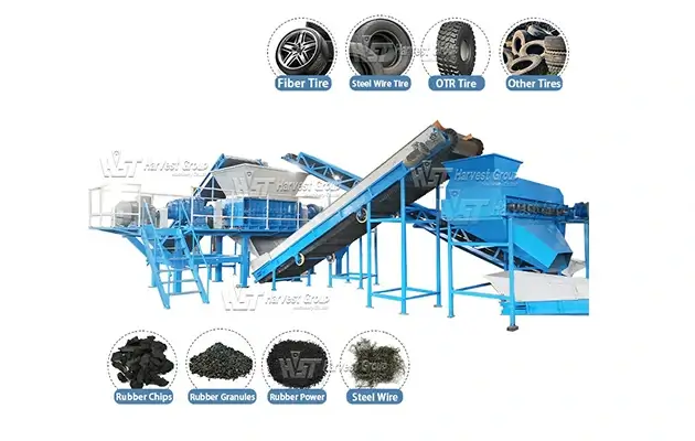
A TDF production line may use a primary shredder followed by screening and oversize return. Some buyers accept a controlled amount of steel because it can be useful in cement-kiln processing, while other users require additional steel removal. The plant should be configured around the fuel consumer’s written size, wire, moisture and contamination limits.
Mulch for landscaping or playground use must be adequately cleaned and free of hazardous exposed wire. A typical rubber mulch production line therefore includes steel liberation, more than one magnetic-separation point, fiber removal and size classification after primary shredding. Coloring and surface treatment may be added according to the product.
Primary chips cannot be sold as crumb rubber simply because they have passed through a shredder. They normally move through a rasper and granulator, with magnetic and air separation positioned according to the degree of steel and fiber liberation. Screened material that remains too large is returned to the appropriate machine rather than being mixed into the finished fraction.
A rubber powder line works best when its feed is already low in steel and textile fiber and is reasonably uniform in size. Sending poorly cleaned chips directly to fine grinding increases wear, heat and product contamination. The quality of the coarse shredding and separation stages therefore affects the efficiency of the final mill.
Tire chips and tire-derived aggregate can be used in drainage, lightweight fill and other civil works, but acceptable particle size, exposed steel and cleanliness vary by project and jurisdiction. Equipment should not be selected from the end-use name alone; the buyer’s material specification must be reviewed first.
Good output is not defined only by appearance. A useful quality check records the size distribution, oversize percentage, exposed wire, total steel content, textile fiber, dust and hourly throughput under known feed conditions. The required limits depend on whether the material will be sold as TDF, processed into mulch or sent to granulation.
A visual sample can reveal long strips, uncut bead sections or excessive exposed wire, but laboratory or weighed separation tests are needed when a buyer specifies a numerical purity. Sampling should cover more than one point in the production run because tire mix, cutter temperature and blade wear can change the result over time.
Operators should use the machine manual and lockout procedure before inspection. The table below is a starting point for diagnosis, not a replacement for checking the actual equipment.
| Observed Condition | Possible Cause | First Checks |
| Frequent automatic reversing | Feed surges, concentrated bead wire, foreign metal, dull cutters or an unsuitable load setting | Pause the feed, inspect the tire mix and chamber, then review current or torque history |
| Capacity falls gradually | Cutter wear, increased clearance, slower feeding or a change from PCR to heavier TBR material | Compare cutter condition, feed composition and motor load with the original operating record |
| Too many oversize pieces | Worn hooks, damaged screen, overloaded return loop or inadequate recirculation | Check cutters, sizing equipment and the balance between fresh feed and returned material |
| Rubber wraps around the shafts | Worn or incorrectly set clearing parts, unsuitable feed pieces or excessive internal clearance | Stop and lock out the machine before checking cleaners, spacers and chamber buildup |
| Excessive steel in downstream rubber | Steel has not been fully liberated, magnet position is poor or conveyor burden is too deep | Inspect liberation after the rasper, magnetic field coverage, belt speed and material depth |
| Abnormal vibration or impact noise | Foreign object, loose component, bearing problem or damaged rotating part | Stop the line safely and inspect before restarting |
One of the most useful maintenance practices is to record motor current, throughput, reversal frequency and cutter service hours. A trend usually shows deterioration earlier than a single visual inspection.
Start with the material and the sales specification, not with a motor rating or an advertised tons-per-hour figure. The correct tire recycling equipment configuration depends on what enters the plant, what must leave it and how many hours the line will operate each day.
| Project Information | Why It Matters |
| Tire categories and their percentage in the feed | A mixed PCR/TBR stream creates a different torque and wear profile from PCR alone |
| Maximum tire diameter, width and weight | Confirms whether whole-tire feeding is possible and whether pre-cutting is required |
| Required finished size and allowable oversize | Determines cutter configuration, screening method and return load |
| Steel and fiber limits | Determines whether a rasper, multiple magnets and fiber separation are needed |
| Target net capacity and daily operating hours | Defines the required continuous duty, buffer capacity and maintenance schedule |
| Local voltage, frequency and control standard | Affects motors, electrical cabinet, protection devices and commissioning |
| Available floor area and loading method | Influences conveyor direction, platform height, return loop and safe service access |
A useful supplier proposal should show the material flow, installed equipment, expected output under stated conditions, connected power, wear-part scope and the boundary between the supplier’s equipment and the buyer’s utilities. Whenever possible, request a test using a tire mix close to the planned feed rather than relying only on an unloaded machine video.
No. A primary shredder makes coarse pieces and opens the tire structure. Crumb rubber production needs further steel liberation, magnetic separation, fiber removal, granulation and screening. Fine powder requires an additional grinding stage.
Not exactly. Cutter thickness influences strip width and cutting behavior, but chip length and maximum size also depend on hook geometry, tire movement, screen opening, cutter wear and oversize recirculation. A guaranteed output specification must describe the complete sizing system.
No. Many primary double-shaft machines use open discharge and rely on an external screen plus a return conveyor when controlled sizing is required. Other designs include a screen within the machine. The actual configuration should be shown in the process drawing.
It depends on the tire and production target. Whole PCR and many TBR tires can be processed by a correctly sized shredder. Pre-removing heavy bead wire can reduce load peaks and downstream steel burden, especially when thick truck or OTR tires make up most of the feed.
Usually not. A magnet can collect steel that has already been exposed and released, but much of the belt and bead wire may still be embedded in coarse rubber. A rasper or another liberation stage is normally required before high steel-removal efficiency can be achieved.
Capacity is affected by tire type, tire size, feed consistency, target output, screen opening, return percentage, cutter condition and allowable motor load. A throughput figure is meaningful only when these test conditions are stated.
A tire shredder works by combining controlled feeding, low-speed high-torque drives and counter-rotating cutters to open reinforced tires and reduce them to manageable pieces. Reliable output then depends on load control, cutter condition, screening and the correct treatment of oversized material.
The best configuration is determined by the tire mix and the product specification. A TDF plant, a wire-free mulch line and a crumb rubber plant may all begin with primary shredding, but their downstream equipment and quality targets are different.
To prepare an equipment configuration, provide the tire type, maximum diameter and width, required output size, target tons per hour, daily operating time and final steel or fiber limit. These details make it possible to select a shredder and downstream system based on the real project rather than a generic capacity claim.