Global waste-tire volumes keep climbing and more countries are tightening environmental rules. Many investors rush to buy shredders, granulators and mills, but overlook one quiet factor that decides whether a plant makes money or loses it: layout and workflow design.
With the same machines, two tire recycling plants can show a gap of 20–40% in capacity and more than 30% in operating cost, simply because the equipment was arranged differently. This guide focuses on the engineering side of a tire recycling project—how to plan the site, organize each production zone and choose the right layout model so that the line runs smoothly from the first day of operation.
The content applies to both compact 300 kg/h lines and industrial plants above 3 tons per hour.
A plant layout is not just “putting machines in a building”. It is a design exercise that should help you:
Cut energy consumption by shortening conveyor runs and avoiding unnecessary lifting or backflow of material.
Increase effective throughput by keeping feeding stable and preventing bottlenecks between sections.
Improve product purity by separating dusty, fiber-rich and fine-powder zones so they do not contaminate each other.
In a typical one-ton-per-hour plant, a compact, straight workflow can save several hours of idle time each week and noticeably lower the kWh per ton of finished product.
A thoughtful layout also affects how resilient the factory is over the years:
High-vibration machines such as primary shredders can be placed away from precision screens and packing scales, extending their life.
Space can be reserved for future environmental equipment—cyclone dust collectors, silencers, additional filters—so upgrades do not require tearing the building apart.
If you leave space along the line for extra mills or granulators, capacity can later be doubled without rebuilding the workshop.
Imagine two plants with the same one-ton-per-hour equipment set:
The first plant uses a clean, linear material flow. Conveyors are short, the dust system is close to the dust sources, and maintenance aisles are wide enough for easy service. It runs close to its design output and keeps energy use low.
The second plant placed machines wherever there was space. Material has to travel long distances, overlap and even cross itself. Frequent blockages and cleaning reduce daily output and raise energy consumption.
On paper the investment looks similar; in reality one plant may earn more than twice the yearly profit of the other.
For layout purposes it is useful to group the tire recycling process into a few engineering zones instead of listing every step as an isolated operation. The names of the machines may vary, but the logic of the material flow is largely the same.
This is the starting point where trucks unload scrap tires. The area usually includes:
A small storage yard
Optional tire debeaders to remove bead wires
The feeding point of the primary shredder
It should be close to the plant entrance to minimize forklift travel. The floor must be durable enough to handle heavy tires and loaders, and there should be a separate bin for collected bead wires.
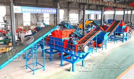
Here whole tires are cut into rough pieces. A heavy-duty shredder and a discharge conveyor with magnetic separation form the heart of this zone.
Key layout ideas:
Provide a reinforced concrete base to absorb vibration.
Reserve enough vertical space over the hopper so that forklifts or cranes can feed complete tires safely.
Position the drum magnet immediately after the discharge to capture loose steel before it travels further into the plant.
The output is typically 50–150 mm shreds stored briefly in a buffer bunker or moved directly to the next zone.
Secondary shredders or rasper machines reduce shreds to about 10–30 mm chips. This section should be kept relatively close to the primary shredder to avoid long, power-hungry conveyors.
Good practice includes:
L-shaped or short straight conveyors between machines to save space.
Ventilation or cooling around the rasper to keep material temperature under control.
Service aisles wide enough for technicians to change wear parts without dismantling other equipment.
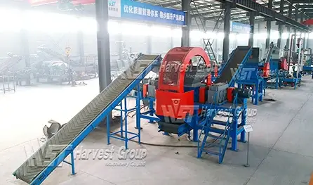
This zone turns chips into high-value crumb rubber and removes textile fiber at the same time. It usually houses granulators, air separators, zig-zag classifiers, cyclones and dust collectors.
Layout considerations:
Install granulators on vibration-damping pads so their movement does not disturb screening accuracy.
Place the air separator and cyclone where the roof is high enough to accommodate them; gravity helps separation.
Enclose the fiber collection area to prevent light fluff from drifting back into the plant.
Well-designed airflow and equipment positioning can push fiber removal efficiency above 98% and keep the workshop visibly cleaner.
If the plant produces fine mesh rubber powder, a separate, more isolated grinding area is recommended. It may include mills, fine screens and high-intensity magnets, followed by packing machines and finished-product storage.
This zone benefits from:
Acoustic insulation, as grinding machines generate more noise.
Dedicated cooling systems to keep rubber temperature in a safe range.
Short, direct paths from screens to bagging equipment so different mesh sizes are not mixed.
Finished crumb or powder can be packed in bulk bags, smaller sacks or silos, depending on the customer base.

Transport cost is one of the main drivers of overall project economics. An ideal location:
Lies within a short distance of a main road so trucks do not have to pass through dense residential streets.
Offers rail access if yearly volumes are high enough to justify bulk shipping.
Stays within reasonable reach of a seaport when products or feedstock are traded internationally.
Even a few extra kilometres per trip can quietly eat into profit over the lifetime of the plant.
Tire recycling is energy-intensive. When evaluating a site, check:
Availability of three-phase industrial power suitable for your target capacity.
Options for a backup generator to protect against outages and material hardening in machines.
Water supply for cooling and cleaning, as well as a feasible way to treat and discharge process water.
Modern projects must satisfy both regulators and neighbours. Good practice includes:
Keeping an appropriate distance from schools and residential areas.
Planning green belts and noise barriers around the plant boundary.
Making sure the land zoning allows industrial activity and that soil protection measures are in place.
Communicating early with local communities and, where possible, offering employment opportunities.
A plant that respects its surroundings faces fewer complaints and enjoys more stable operation.
Different workshop shapes and capacities call for different arrangements. Three models are widely used and easy to adapt.
A U-shaped arrangement is popular for small plants up to about 800 kg/h where floor space is limited.
Characteristics:
Equipment follows a curved path and finishes close to the starting point.
Overall conveyor length is short, which lowers power consumption.
Operators can stand near the centre of the “U” and oversee several machines at once.
This model works well in workshops of roughly 150–250 m².
When the building is rectangular or when future expansion is likely, an L-shaped layout often fits best.
Advantages:
The “corner” of the L can host auxiliary systems such as fiber separation or dust collection.
Additional grinding or screening stages can later be added along one arm of the L without disturbing the rest of the line.
Material flows in one direction without crossing, reducing cleaning effort.
It is a good choice for lines around 800 kg/h to 2 tons per hour in spaces of approximately 300–600 m².
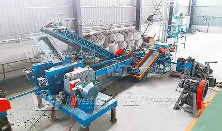
Large plants processing several tons per hour benefit from a straight-through design.
Benefits:
Material enters at one end and finished products leave at the other with no backtracking.
Maintenance access is simple: every machine has its own service corridor.
Two parallel lines can share some infrastructure while maintaining independent operation.
This approach typically requires 800–2,000 m² but offers the highest efficiency and is easy to understand for operators and inspectors alike.
Passenger car tires, truck tires and large OTR tires place very different demands on machinery. Heavier, thicker tires may require pre-cutting or stronger shredders with reinforced wear parts. Over-specifying the machine for very light tires wastes energy; under-specifying it leads to frequent breakdowns.
It is tempting to buy the largest machine available, but an oversized shredder running mostly empty wastes electricity. A better approach is to:
Estimate daily tonnage and working hours.
Choose machines whose rated capacity is slightly above that requirement to allow for peaks.
This keeps both investment and energy use under control.
Plants focusing on rubber mulch or playground granules may not need fine grinding at all. Skipping the powder stage lowers the initial investment and simplifies layout.
On the other hand, projects targeting high-mesh rubber powder for asphalt modification or reclaim rubber must reserve a dedicated grinding and fine screening area. The layout should ensure a clean separation between granulation and powder zones to protect purity.
Semi-automatic lines with manual feeding and bagging require more workers but cost less upfront. Fully automated systems with PLC control, automatic feeding and automatic packing reduce labour and stabilize product quality, at the price of higher initial investment. Layout design should reflect the chosen level of automation: automated lines need more sensors, cable routing and maintenance access around control cabinets.
Even good equipment can perform poorly if the plant layout contains hidden traps. The following problems appear again and again in real projects.
If dust collectors are installed at the edge of the workshop and connected with long, narrow pipes, suction will be weak. Dust escapes at transfer points, settles on equipment and ends up in finished product. Locating dust collectors close to high-dust machines and keeping duct runs short improves both working conditions and product quality.
Textile fiber is light and easily carried by air currents. When the fiber separation area is next to the fine grinding zone, some fibers inevitably drift back, raising the fiber content of powder and leading to customer complaints. Physical separation, partition walls and directed ventilation help keep the zones independent.
In some plants machines are squeezed tightly against walls or other machines. Changing a shredder rotor or a screen then requires partial disassembly of the surrounding line, causing long shutdowns. Leaving at least a workable maintenance corridor around each critical machine pays for itself many times over in reduced downtime.
If packed material must be transported across the entire building to reach the truck loading area, forklifts spend unnecessary time in transit. Placing packing and storage close to the exit creates a simple “screening – packing – loading” flow and frees operators for more productive work.
Screens and precision equipment should not share foundations with heavy shredders or mills. Otherwise, transmitted vibration leads to cracked frames, torn screens and poor separation efficiency. Separate foundations or damping elements significantly reduce vibration transfer.
When every square metre is filled during the first installation, later upgrades become painful. A layout that leaves some open space for an extra mill, another granulator or a second packing line makes long-term growth much easier and cheaper.
Good engineering design does not end with a drawing. Once the plant is running, three ongoing strategies keep profitability high:
Secure low-cost feedstock. Long-term agreements with tire shops, transport companies or waste-management firms can turn scrap tires into a paid service rather than a raw-material cost.
Segment products by quality and mesh size. High-purity fine powder can be sold to demanding clients such as asphalt or reclaim rubber producers, while coarser granules and mixed materials can serve playground, flooring or fuel markets.
Manage energy and maintenance carefully. Aligning production with off-peak electricity tariffs, cleaning transfer points regularly and following a preventive maintenance plan can save significant money over the life of the plant.
A successful tire recycling business is not built by machines alone. It is built by how those machines are arranged, how material flows through them, and how the plant interacts with its site and community.
From site selection and zoning to layout choice and equipment configuration, every decision should serve one goal: stable, efficient and profitable conversion of waste tires into valuable rubber products.
Whether your project is a compact 300 kg/h line or a multi-ton industrial facility, remember three principles:
Keep material moving in one direction.
Separate noisy, dusty and precision zones.
Reserve space for future growth.
With a well-designed layout and workflow, your tire recycling plant can start generating reliable profit from the first day of operation and stay competitive for many years to come.